“It may be the first dedicated guitar effect”: From its journey from amp to stompbox to how it works, this is everything you need to know about tremolo

Electronic tremolo employs circuitry to mimic musical effects that have traditionally been produced by playing techniques on certain instruments.
If you were ever required to memorise Italian terms for music theory exams, you may be familiar with the word tremolando, and there’s even notation for tremolo on musical scores. Tremolando from Italian translates as ‘trembling’ and can refer to fluctuations in volume, the fast repetition of a single note or rapid alternation between two notes.
A string player might achieve these effects by quickly moving a bow back and forth, and a balalaika, mandolin or guitar player may employ fast alternate picking using a plectrum. And we’re all familiar with the hammering on and pulling off that so many blues and rock players use to get that two-note trill.
Church organs with tremolo started appearing as early as the 16th century. It was mechanical, rather than electronic, and was produced by opening and closing diaphragms in the pipes to modulate air pressure. In addition to modulating volume, this also caused fluctuations in pitch.

Tremolo arms notwithstanding, we tend to refer to pitch fluctuations as vibrato, rather than tremolo. But there is a long tradition of using both terms interchangeably and maybe Leo Fender was attempting to distinguish his whammy bar system from Paul Bigsby’s. Later, when Fender developed volume-modulating tremolo circuits, the company was almost obliged to describe the effect as vibrato.
Electro-Mechanics
DeArmond first designed an electronic tremolo for the electric Storytone piano during the 1940s. Shortly after, the company’s ‘Tremolo Control’ was offered as a standalone unit and it may be the first dedicated guitar effect.
A motorised spindle agitated a canister containing electrolytic fluid, which varied the amount of audio signal going to ground and therefore caused volume to fluctuate. Famous users included Bo Diddley, Muddy Waters, Billy Gibbons and Duane Eddy, who used his on Rebel Rouser.
All the latest guitar news, interviews, lessons, reviews, deals and more, direct to your inbox!
Oscillation
Tremolo circuits began appearing in guitar amps around the late ’40s and companies such as Gibson, Multivox and Danelectro were early adopters. Fender and Magnatone amps became renowned for their tremolo effects – but didn’t get started until 1955.
Purely electronic onboard tremolo offered greater convenience and long-term reliability than mechanically driven tremolo units that required a separate power source.

Most amp tremolos are based on a circuit called a phase shift oscillator. The circuit uses a single valve stage to generate a sine wave at a frequency somewhere between 1Hz and 10Hz with a loop connected between the anode and grid employing a three-stage capacitor/resistor (CR) network.
The gain stage creates a 180-degree phase shift and each capacitor in the CR network charges off the anode voltage and then discharges to ground through resistors. The resulting delay at each stage provides a 60-degree phase to bring the total phase shift through another 180 degrees. The combined phase shift is 360 degrees, which makes the feedback positive, rather than negative.
The loop gain must be set at unity or higher, so a large anode resistor to maximise gain along with a cathode that is fully bypassed below the oscillation frequency are usually combined with a high-gain 12AX7/ECC83 valve. Just like guitar and amp feedback, the tremolo needs something to get the loop started.
With a guitar, it’s a case of playing in close proximity to an amp at a sufficiently high volume. The tremolo circuit’s input signal comes from its output signal and the oscillator actually gets going from the noise that’s inherent to the circuit. This is why it can take a moment for the tremolo to reach full strength after footswitch activation disconnects the loop from ground.
While the names may vary, most amp trems have speed and depth controls. Oscillation speed is adjusted by combining a potentiometer with a fixed resistor in the first shunt position of the feedback loop. The resistor sets the minimum speed and the potentiometer increases the overall resistance to increase the oscillation frequency.
Wiggling Roaches
We’ve established how a single valve stage can operate as an oscillator, but how can the alternating current be used to create a tremolo effect? One way is to combine the oscillator output with the bias voltage of fixed bias power valves. This causes the bias voltage to vary at a rate set by the oscillator, and as bias goes up and down, so does the output of the power valves.
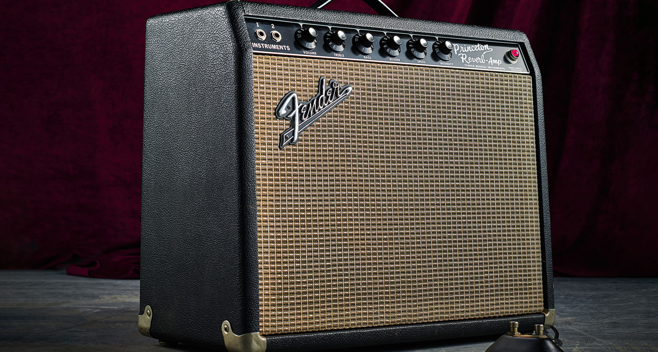
This is sometimes called ‘bias wiggle’ tremolo and in this instance an intensity control determines how much of the oscillator output reaches the valve bias circuit. With some variations in component values, this is the circuit Fender used in the Tweed Vibrolux, brown Princeton and the Princeton Reverb.
The difference between the Tweed, brown- and black-panel bias wiggle tremolos is more about feel than sound quality, with the earlier amps seeming deeper and swampier, and having a slightly different speed range. But it’s easy enough to swap a few components to make a black-panel Princeton sound more brown-panel like, or vice versa.
For cathode-biased amps, the oscillator output isn’t applied in the same way. Instead, it’s usually routed to a stage earlier in the signal path and a common point is the cathode of the phase inverter valve. This was Fender’s solution with the Tweed Tremolux and the Vibro Champ.
Amps such as Marshall’s 18-watt and various Vox and WEM amps applied the tremolo modulation even earlier in the signal chain. The effect isn’t as deep and throbby as bias wiggle tremolo, and in some amps it can sound lacklustre.
Some amp builders prefer to modulate preamp valve bias, rather than power valve bias. Sometimes the power valves have to be biased on the cool side to get the tremolo working properly, which may compromise tone, and some argue that it puts additional stress on the power valves.
The optocoupler is often called the ‘roach’ because it has a black body with four ‘legs’ sticking out, and many refer to this as optical tremolo
From the mid-’60s onwards, Fender equipped amps including the Deluxe Reverb, Twin Reverb, Vibroverb, Tremolux, Pro, and others, with a new tremolo circuit. It used both sides of a dual triode valve and an optocoupler. The optocoupler is often called the ‘roach’ because it has a black body with four ‘legs’ sticking out, and many refer to this as optical tremolo.
The first triode is configured as an oscillator in the usual way, but the anode is connected to the grid of the second triode, which amplifies the oscillator output. This second triode drives the optocoupler, which is actually a sealed unit containing a neon bulb and a light-dependent resistor (LDR).
The amplified oscillator output varies the amount of light produced by the bulb and the LDR’s resistance is highest when the bulb is dim and lowest when the bulb is bright.
One side of the LDR gets the audio signal from a point in the circuit just before a mixer resistor merges the vibrato channel with the normal channel. The other side of the LDR is connected to ground so as the bulb modulates the LDR’s resistance, the amount of audio signal going to ground varies accordingly and volume level fluctuates at a rate determined by the speed control. The intensity of the tremolo is set by a potentiometer that restricts the amount of audio signal reaching the LDR.
Another name for this is ‘signal shunting tremolo’ and it’s characterised by an asymmetrical response, where the volume rise and fall occur at different rates. It often has a tad more shimmer and flutter than bias wiggle tremolo, and much depends on the characteristics of the bulb and the response and recovery times of the LDR.
Pitched Harmonics
Many consider the brown-panel era ‘harmonic vibrato’ to be Fender’s ultimate tremolo design. The complex circuit requires multiple triode stages, with some designs utilising four and later versions five.
This added to the build cost, so it mostly featured on Fender’s top of the range amps such as the Vibrosonic, Bandmaster, Super, Pro, Concert, Twin and Showman.
In the simpler circuit, the output of a regular oscillator stage modulates the gain stage of a 7025 triode via an intensity control. This modulation signal is split after the intensity control to feed another gain stage that flips the oscillator polarity and modulates the other half of the 7025.
The clever bit is that the audio inputs to the 7025 are sent through high- and low-pass filters, and when the low frequencies are in a positive tremolo cycle, the high frequencies are in a negative cycle. The effect has been described as a pseudo-vibrato because it appears to pitch shift, but it is actually tremolo with phasing and it results in a complex, hypnotic and beautiful effect.
The later circuit does the same job, but the oscillator feeds a cathode follower that drives a 12AX7 stage configured as a phase inverter. The anode and cathode outputs modulate the 7025 gain stages and, as before, the 7025 audio outputs are combined to drive the phase inverter for the power valves.
Pedal Tones
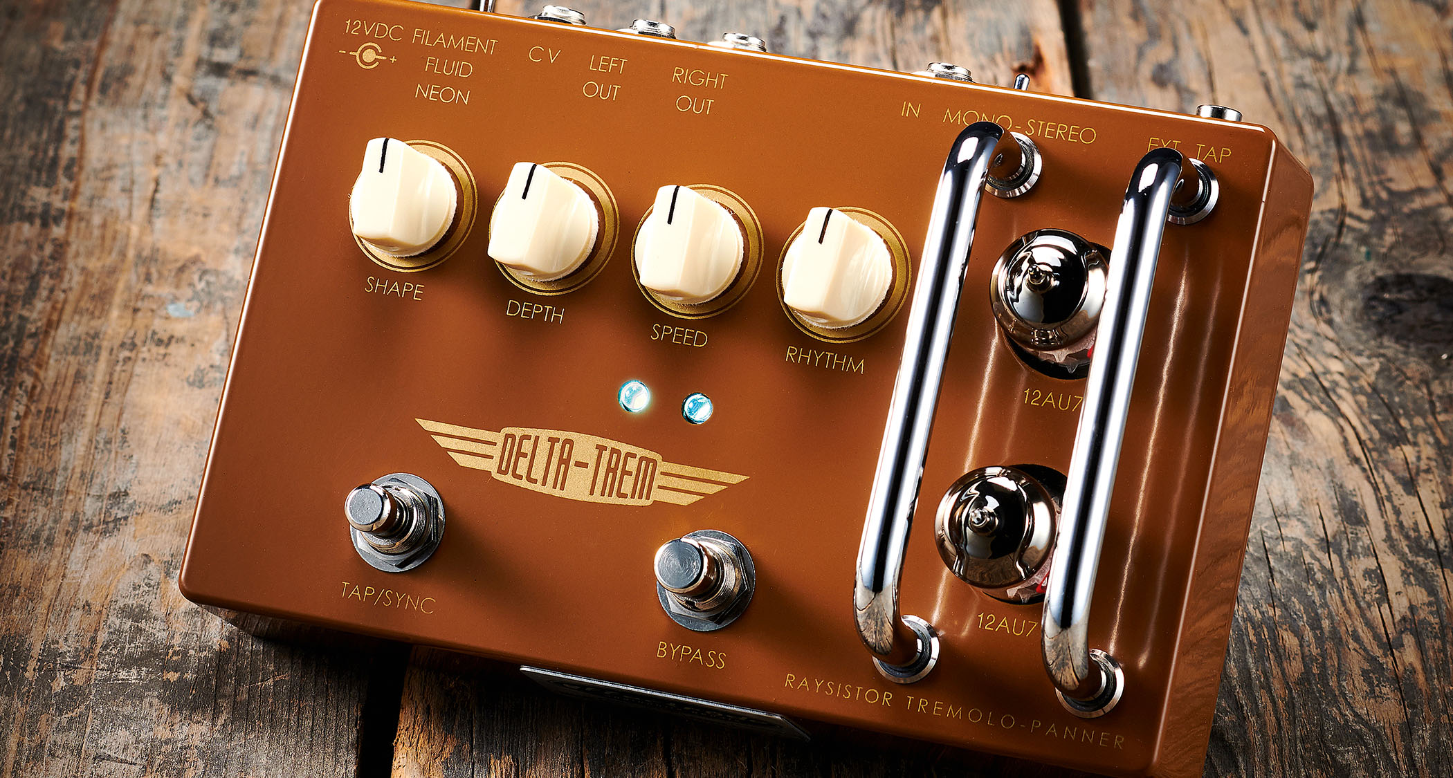
We’ve focused on the various varieties of amp tremolo because most tremolo pedals are designed to emulate classic circuits. Some do so using valves, but most run on JFETs, transistors or op-amps. For modern optical tremolo, an LDR is usually combined with an LED, rather than a neon bulb, or instead builders use sealed units called vactrols.
If harmonic tremolo is your thing, then choosing the pedal route is a cheaper and easier solution
If harmonic tremolo is your thing, then choosing the pedal route is a cheaper and easier solution, and some pedals even allow you to switch between harmonic and regular tremolo modes.
Other modern features onboard include tap tempo and expression pedal control. Some pedals also allow you to modify the oscillator waveform from sine to sawtooth or triangle, or even switch between symmetrical and asymmetrical to achieve your preferred feel.
Huw started out in recording studios, working as a sound engineer and producer for David Bowie, Primal Scream, Ian Dury, Fad Gadget, My Bloody Valentine, Cardinal Black and many others. His book, Recording Guitar & Bass, was published in 2002 and a freelance career in journalism soon followed. He has written reviews, interviews, workshop and technical articles for Guitarist, Guitar Magazine, Guitar Player, Acoustic Magazine, Guitar Buyer and Music Tech. He has also contributed to several books, including The Tube Amp Book by Aspen Pittman. Huw builds and maintains guitars and amplifiers for clients, and specializes in vintage restoration. He provides consultancy services for equipment manufacturers and can, occasionally, be lured back into the studio.


