How to install a new 3-way pickup switch
Our guide to soldering a new switch into your electric guitar - without ruining the circuit
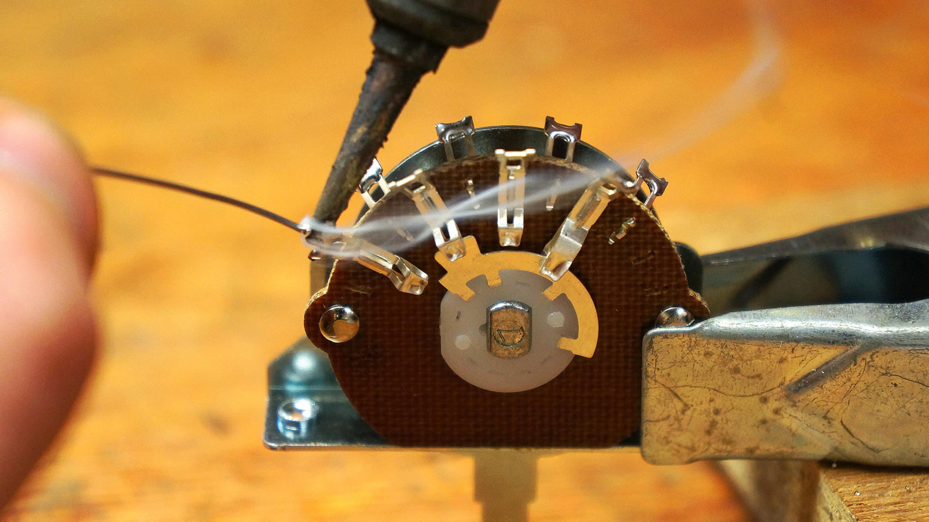
Any moving electrical part on your guitar can wear out. Tone pots and jack sockets are especially prone. And it’ll come as no surprise that switches can become crackly or fail mechanically too - just like this article's repair job.
The old switch doesn’t have any ‘clicks’, so it won’t stay in position, and, as such, it’s earned itself a ticket to the landfill. Here’s the thing though; the new switch has a different pin layout which confuses things a little; there’s a more complicated circuit than expected to keep an eye on too.
To boot, we’ll show you how to ID pickup color codes if you have an unusual pickup. The switch we’ll be, erm, switching is an Oak Grigsby 3-way item which will replace the bust no-namer example.
The Oak Grisgby one is the more common Fender style terminal layout and we’ll need to use both sides of it.
We like these switches because you can see the workings of them, so, if there’s ever any confusion as to which terminals are getting connected, you can just look!
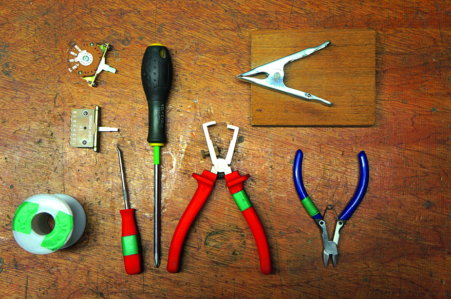
What you need
Skill Level: Medium
- 40 Watt soldering iron
- 60/40 Solder
- Soldering helping hand
- New 3-way switch
- Wire cutters
- Wire strippers
- Handy poker/pick
- Masking tape
- Wiring Diagram (either drawn or downloaded)
- Pickup color code (optional)
- Digital multimeter (optional)
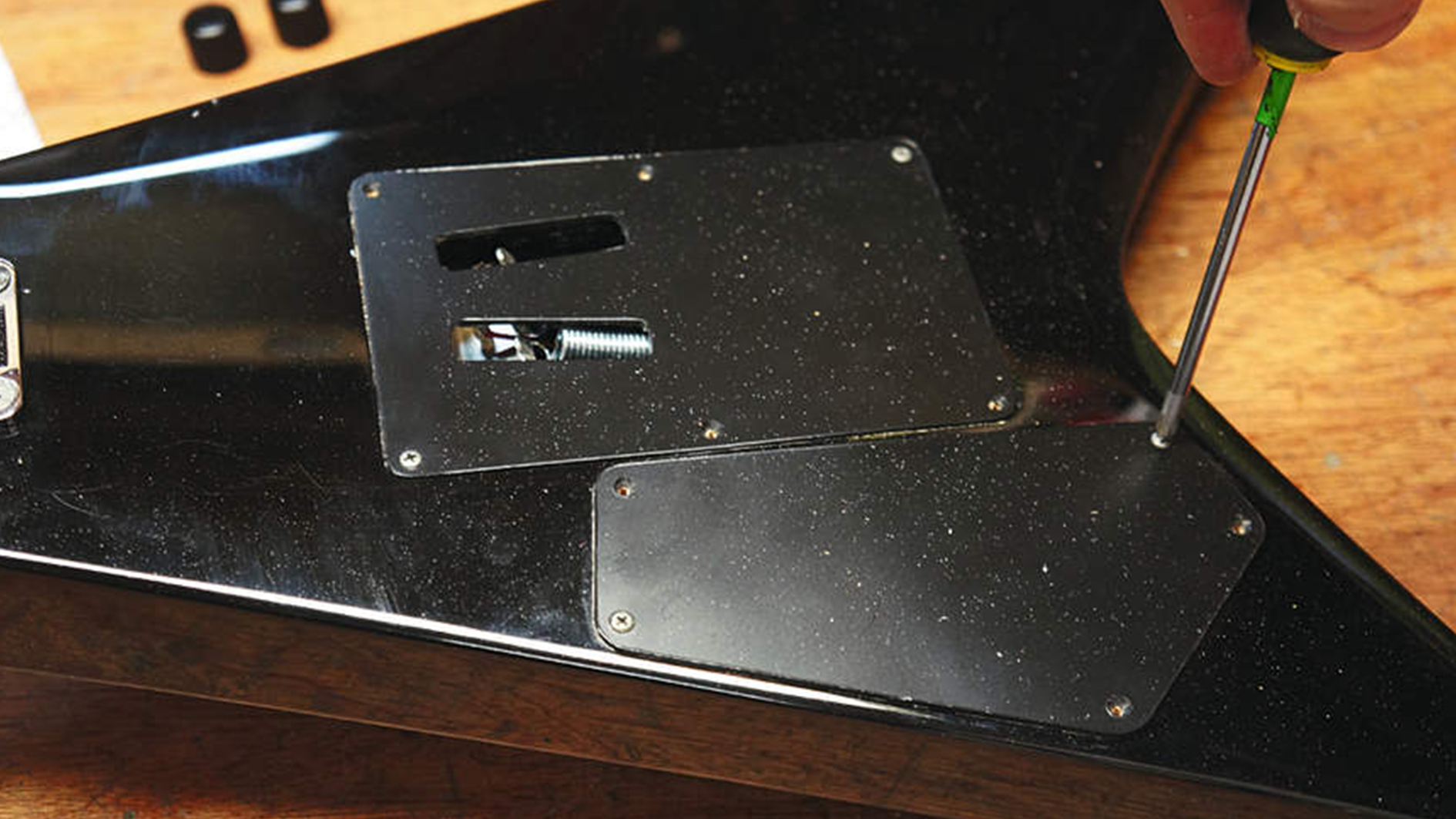
1. Whip off the back plate cover - this will get you access to the electronics cavity where all its guts are hiding. A PH1 screwdriver will do just fine. Our repair here is for a Kramer Vanguard guitar but the principles presented here are fairly general.
All the latest guitar news, interviews, lessons, reviews, deals and more, direct to your inbox!
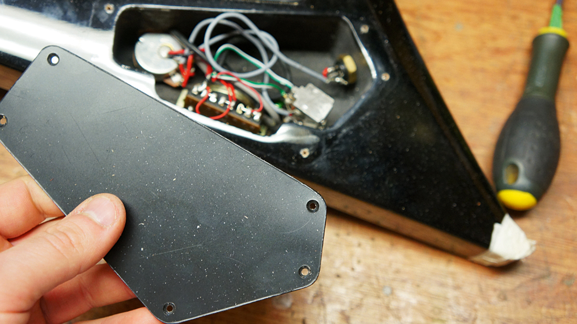
2. Inside, we have a surprise component we weren’t expecting - a push-pull pot. So, we have a master volume, a master tone, 3-way switch and a coil-split function. The push-pull pot has two functions: to turn down the treble (tone), and to cut half of each pickup out - coil-splitting both pickups - by pulling the switch up.
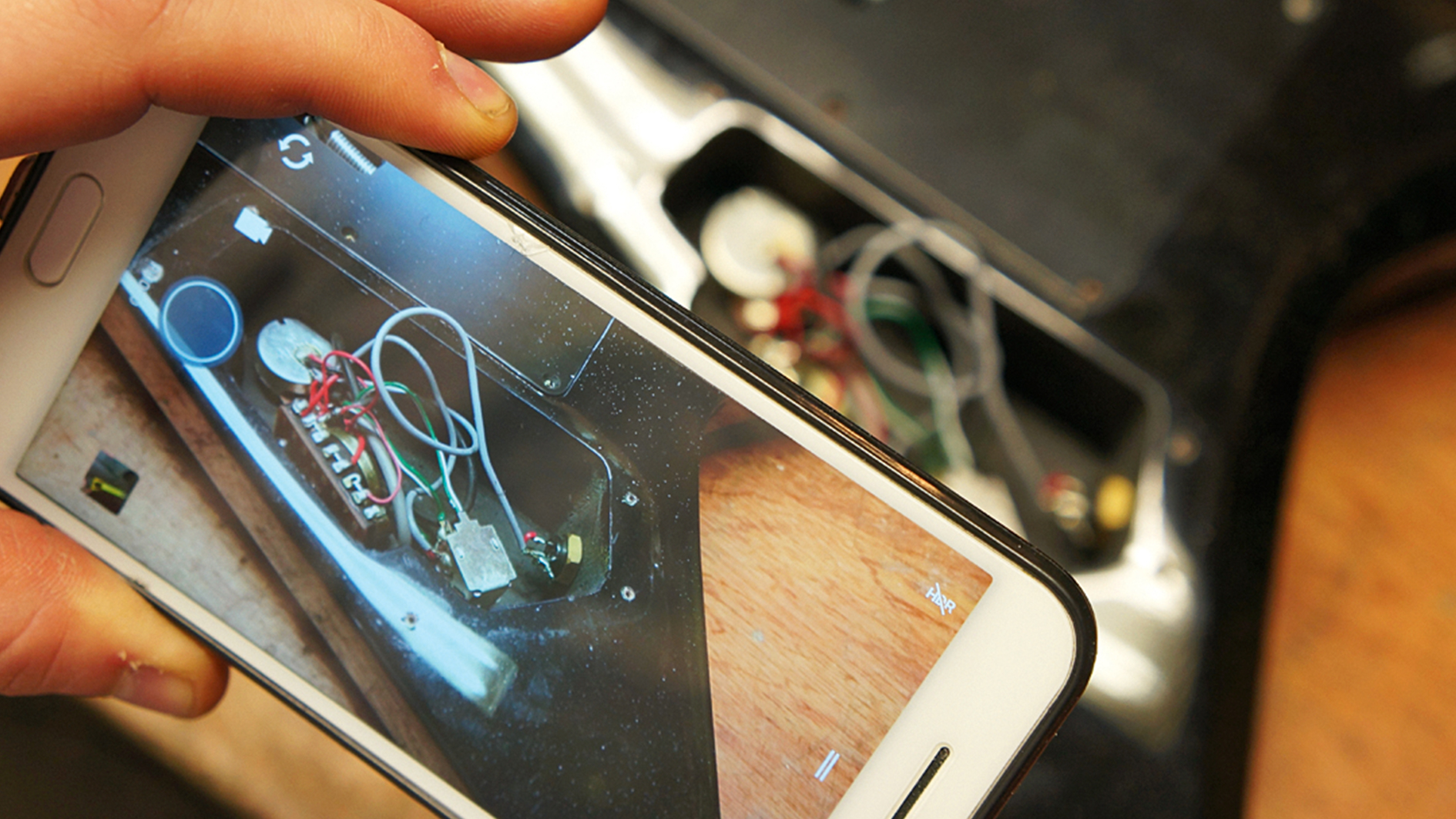
3. Take a snap of the old wiring just in case anything goes wrong. We’re aiming to change just the pickup switch only but chances are a wire may fall off too, especially on an old guitar. Even better would be to draw the wiring diagram.
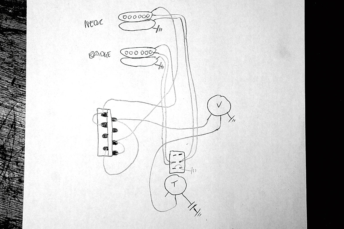
4. Oh look, a diagram! We drew this to lay out the whole wiring diagram, including all the details for the coil-split design and also to put in the new switch. There are essentially two switch designs: one with the solder terminals all in a line and another offset style, which is what Fender tend to use. This diagram converts one style to the other to save head-scratching!
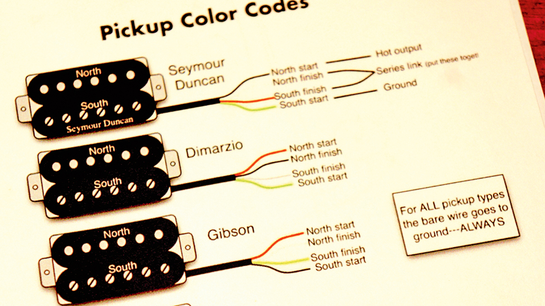
5. Still more theory before we get to the practical exam! Each manufacturer has their own cabling colors, Googling ‘pickup color codes’ will be immensely helpful to learn which wire is what. In our Kramer here, we have the brilliantly daft Quad Rail pickups. You can use the old locations of the wires to skip this step if you’re confident.
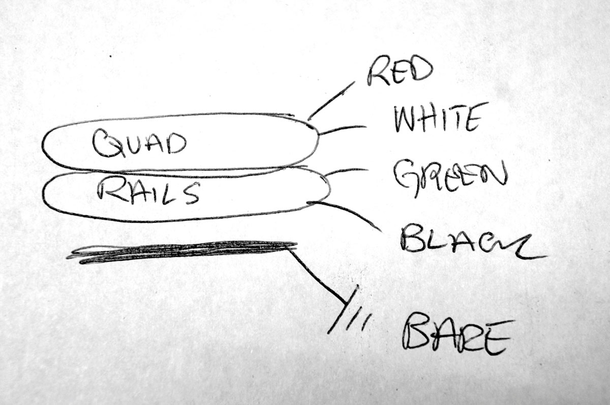
6. Each Quad Rails pickup has four coils connected in series for a whopping output. We figured out the color code for ours by getting a ~6k ohm reading from red + white and the same from green + black using a multimeter. The bare wire is always earth. Here, the green + white is the coil junction that gets sent to the push-pull pot.
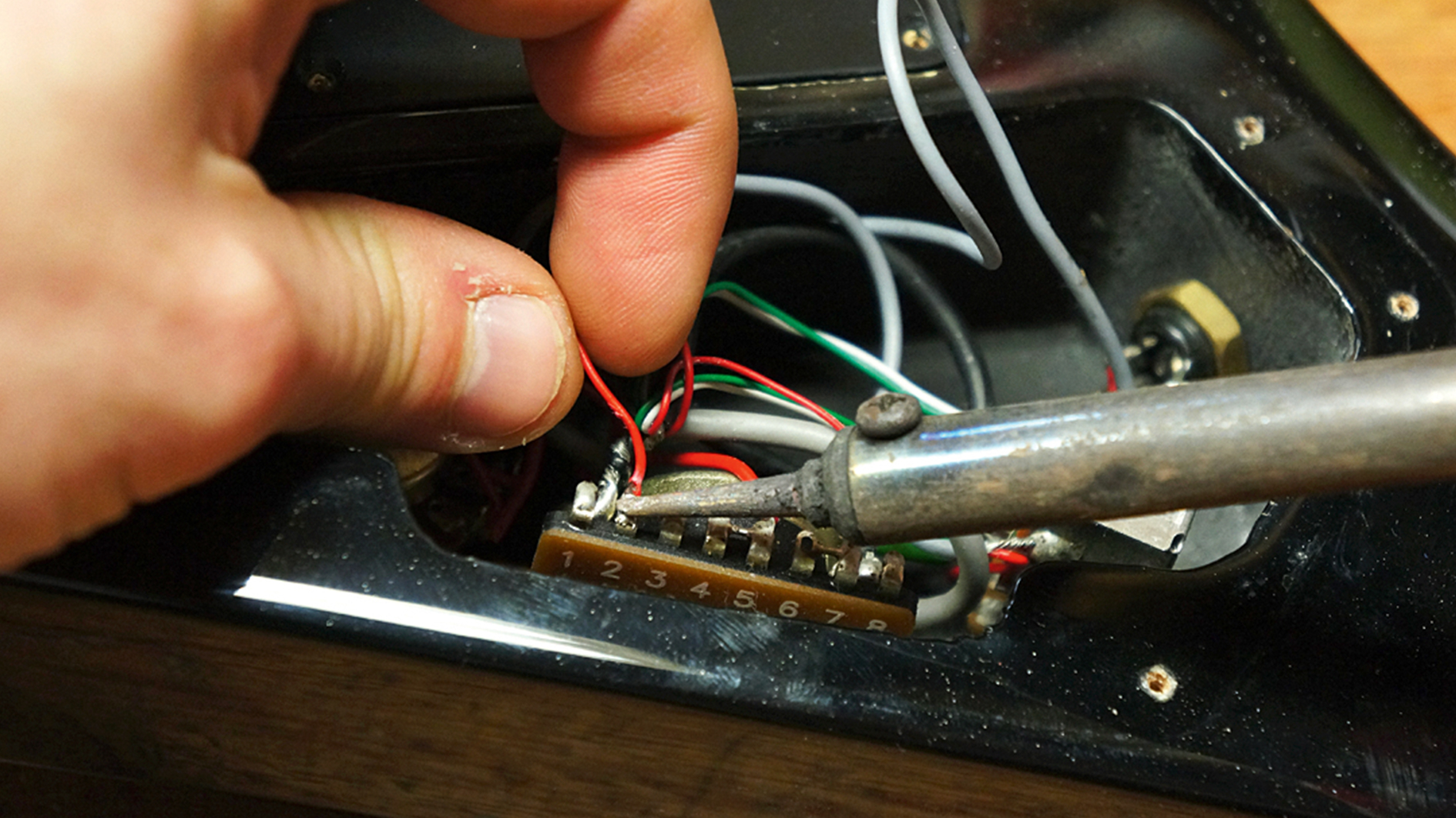
7. Whip out the connections from the old switch by unsoldering them. You could snip them with wire cutters, but then you’d have to strip the wires again, and sometimes there’s not enough wire left. Our switch had ground wires going to the casing of the old switch, we’ll move them to connect to the body of the pots instead.
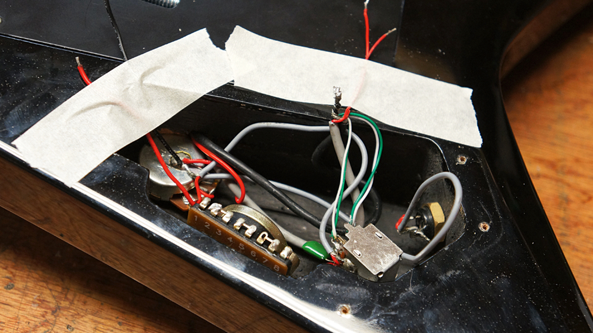
8. Top Tip! Tape wires out the way, when you’re re-soldering the new switch back in the last thing you want is to melt a rogue wire. Unscrew the old switch from the front of the guitar using a PH2 Screw driver, we chose to reuse the old screws as they suited our color scheme!
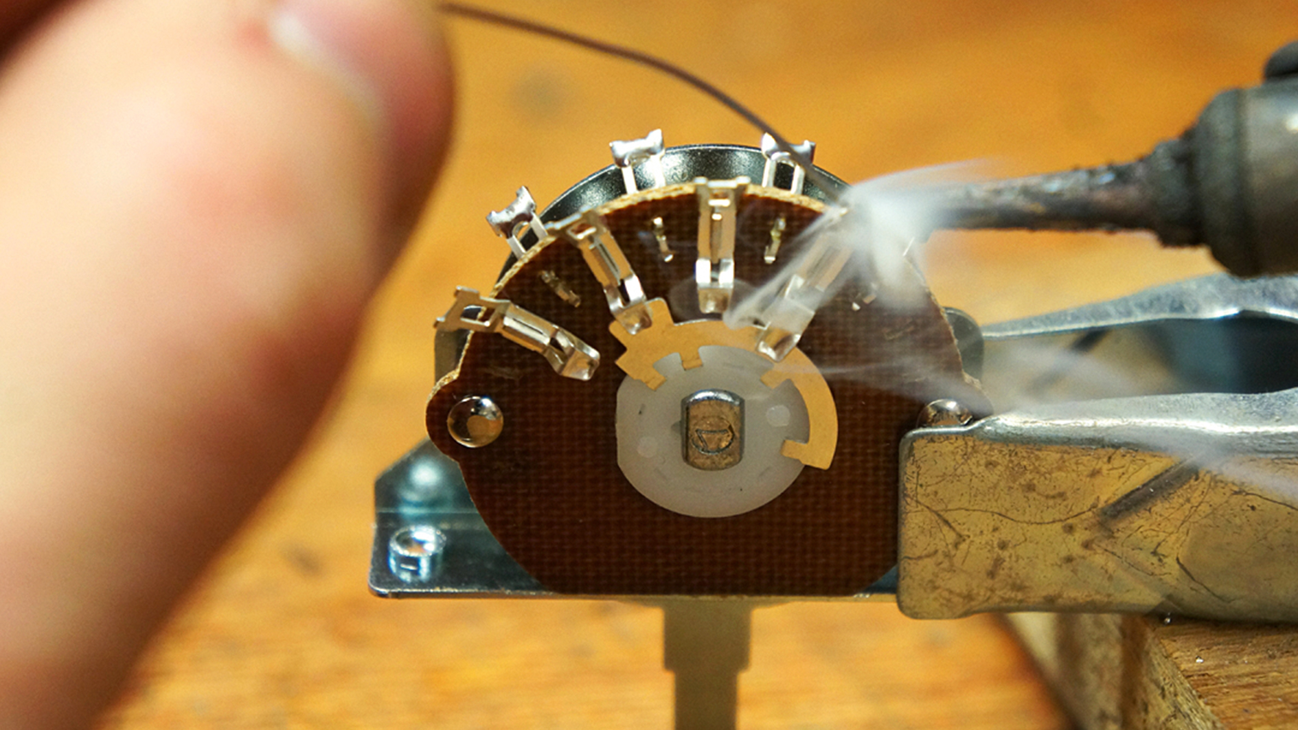
9. We’re preparing the new offset terminal-style switch by tinning each terminal. This will free up a hand when we reattach the wires later, where all we have to do is heat the joint up and melt in the wire, and not have to supply solder at the same time! Use a solder helper to hold the switch in place but be careful not to damage it.
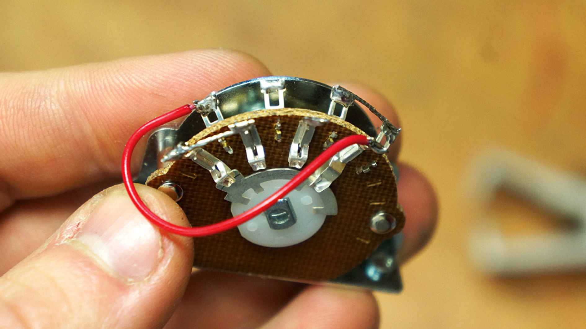
10. Following the diagram, we’ve added some jumper wires onto the switch - this is best done safely clamped in a soldering helper before it goes back into the control cavity. The bare jumper wires are where the pickup ‘hot’ wires will attach, one pickup per side. The red wire connects the two common terminals together.
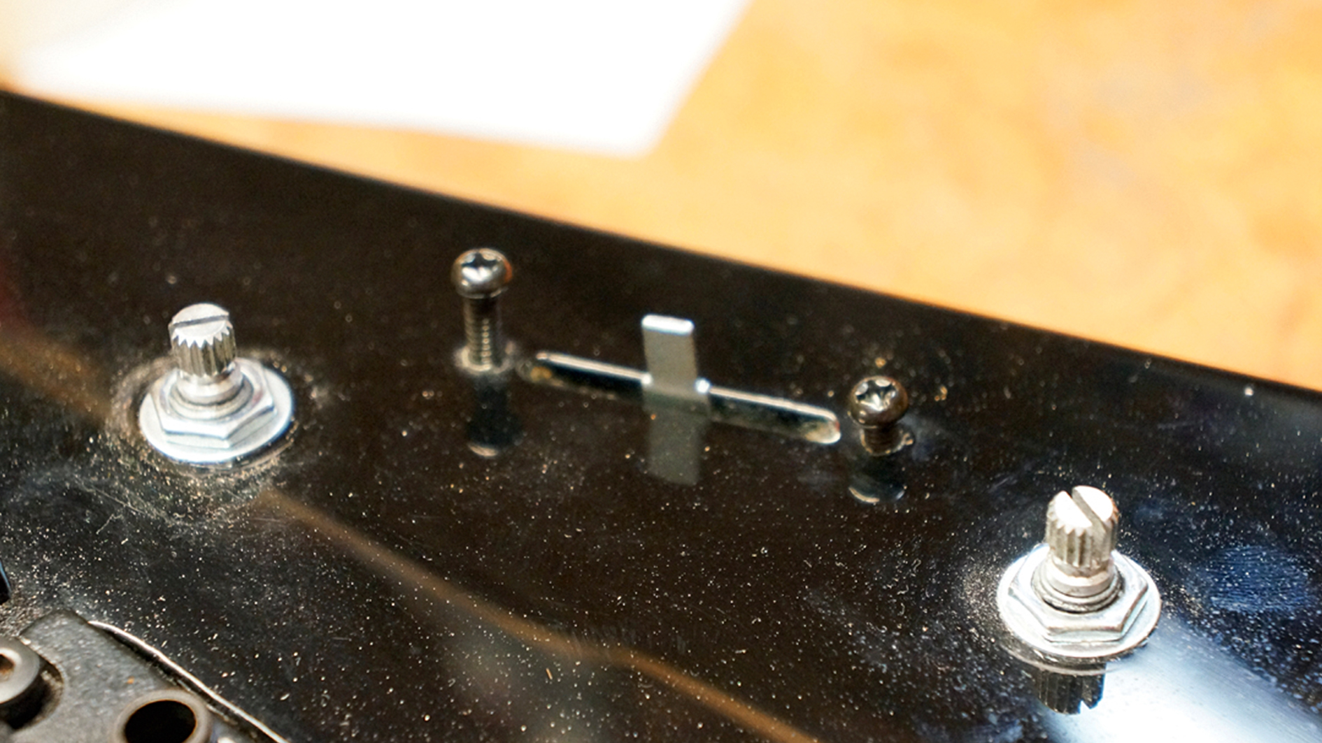
11. Go for it, complete the circuit adding your hot wires and output wire. In our case, we had to re-home two ground wires that used to be attached to the switch body; we sent them to another earth connection on the rear of the pots. Mount the new switch on your guitar with the two bolts to the front.
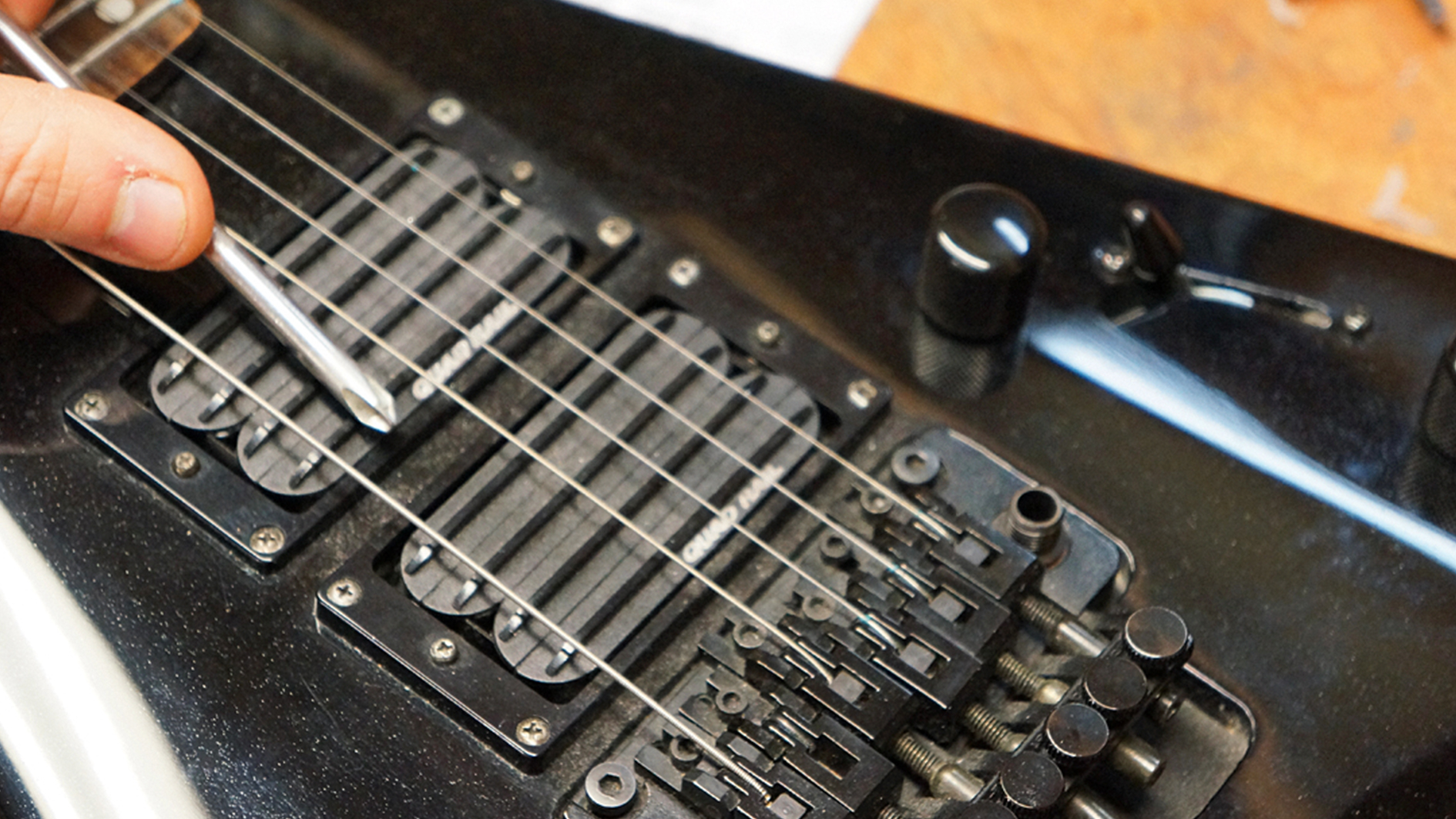
12. Time to test! Plug in, turn up the volume and tap test by tapping a screwdriver onto your pickup. You should hear the pickups working through your amp. If your pickups are the wrong way round compared to the switch then swap the two hot wires around. If you made a mistake, go back to the diagram and see what it could be.
Jack runs an independent guitar setup and guitar repair service in Manchester, England. He serves the musicians of the Northwest of England, working on electric guitars, bass guitars, acoustic guitars and more. Jack has been writing the Fix Your Guitar column in Total Guitar Magazine since 2017.

